Energy Transfer from the Coil
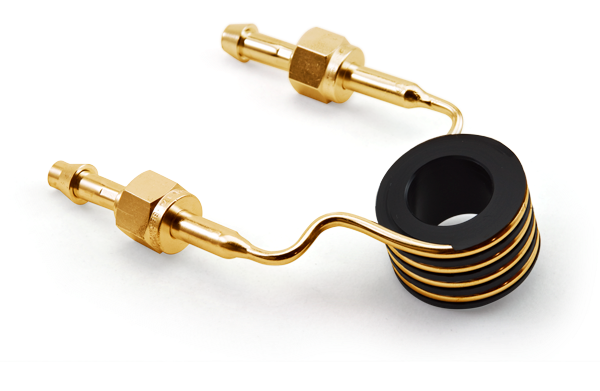
The RF coil is the last component in the RF system of your ICP-OES and ICP-MS that is used to generate plasma. Therefore, the condition and shape of the RF coil can have a major effect on the efficiency of transferring energy to the plasma.
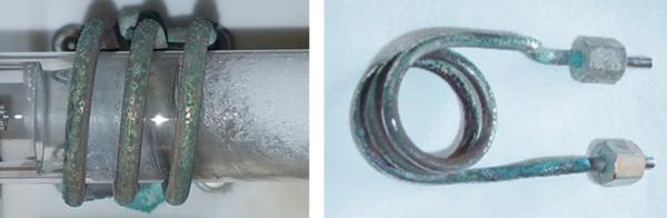
Being exposed to the environment of the torch box, the RF coil is susceptible to corrosion. The greater the corrosion, the larger amount of energy is needed to produce a plasma of the same power. This transfers undue stress on the rest of the electrical components used in the RF system of your ICP-OES and ICP-MS, possibly contributing to premature failure.
Older ICP’s used a power amplifier (PA) tube as part of the RF system. Excessive stress on this component would result in a service call of several thousand dollars. Newer ICP’s utilize a solid-state RF system which, although more modular, would result in an even more expensive service call to replace. Regular replacement of your RF coil reduces the load on the RF generating system and ensures your ICP is running optimally. The suggested rate at which you should replace your RF coil is every 6 months for ICP-MS and every 2 years for ICP-OES. Depending on the laboratory environment your instrument may require more or less frequent replacement. The RF coils pictured in Figure 1 are well past the point of replacement. Coils in this condition increase the stress applied to other components in the RF generating system and can shorten the lifetime of your torch, in addition to the power amplifier or solid-state generator.
There are three factors affecting the transfer of energy from the RF coil:
- Concentricity and alignment - are very important in producing a correctly shaped plasma, which consistently needs to be located in the same position.
- Correct dimensions - being part of the RF system, the coil dimensions are also important in the tuning of the circuit. Slight changes in dimensions can produce small changes in resistance or inductance. These changes can also lead to variations in the shape of the plasma and affect energy transfer from the plasma to the sample.
- Base metal/plating - the most efficient conductor of RF energy is pure silver followed by annealed copper. There is very little difference in the conductivity of these materials but there is a great deal of difference in cost. Copper is used as the base material of all commercially available coils but different manufacturers use different plating materials. Silver has the best conductance and gold has the best corrosion resistance.
The next step is to transfer the energy from the plasma to the aerosol sample. There are two main factors that affect this transfer:
- Argon gas flow rates and quality. Obviously, high-purity argon is required and is generally available although it can be quite expensive, especially in some countries. Higher nebulizer argon flow rates will shorten aerosol residence time and can also cool the plasma, both of which lead to lower intensities.
- The torch containing the plasma. The torch needs to be concentric and of the highest quality quartz. If the outer tube becomes devitrified, the transfer of energy is restricted due to losses incurred by heating on the surface of the outer tube, thereby reducing the available energy for the atoms and ions.
Why Choose a Glass Expansion Coil?
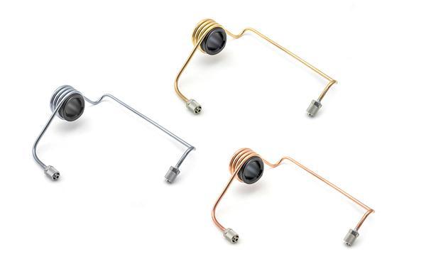
Glass Expansion coils are produced from the highest quality and purity raw materials and plated using proprietary methods to obtain maximum RF transmission efficiency. Examples of copper, gold and silver Glass Expansion RF coils to suit the Agilent 7900 ICP-MS are shown in Figure 2.
Advantages of Glass Expansion RF Coils:
- High purity and consistent plating promote extended coil life
Each coil is supplied on a plastic former ensuring correct dimensions are maintained and allowing easier installation. These formers can be then used periodically to check the coil dimensions, so it is a good idea to keep the former even after coil installation. - Each coil is supplied in a special protective container to ensure correct dimensions are maintained, and the coil arrives corrosion free.
- Correct alignment of the coil with respect to the torch body reduces devitrification of the outer tube and ensures the plasma is concentric within the torch allowing the sample aerosol to travel correctly through the plasma.
In addition to producing the highest quality RF coils, Glass Expansion also simplifies the installation with a “Do-it-yourself” RF coil installation kit. Each kit is designed specific to the ICP model, including an installation tool, spanner and easy-to-follow step-by-step instructions. This way you ensure proper alignment and concentricity each and every time, in addition to saving the cost of a service call and minimizing ICP downtime. Glass Expansion has recently added to its family of RF coils to accommodate more models of ICP-OES and ICP-MS instruments.
